Single Check Valve Couplings
They were originally used for connecting portable air tools and equipments to air lines. Hence ,
they are often referred to as Pneumatic Couplings. Originally they were available from 1/8″ to 1/2″
sizes, upto a pressure of 300 psi ( 21 kg/cm2). However, now they are available up to a 3″ size to
meet new applications.
The Coupler should be installed on the supply end of the line to shut off the fluid supply when
coupling is disconnected.
The adopter has no valving & upon disconnection exhausts the downstream media. Even in liquid
lines, this would not be mechanically detrimental unless fluid loss would interface with a holding
circuit or contaminates the area around it.
Fluids flows from coupler or adaptor
Features :
Interchangeable with standard industrial couplings
High flow capacity.
Anti rusting material for valve.
Minimum force to connect.
Wide variety of end connections.
Applications:
Air supply to small pneumatic tools /machines
Agriculture machinery
Air guns
General air service
Pneumatic pipings
Pneumatic Tools
Pneumatic servo control /systems
Workstations.
For Best Performance:
Use only with recommended media.
Use only with the suggested operating temperature. n Be sure to choose the appropriate type of packing material for your application.
Keep the coupler clean and free of dust .
Use a filter for fluid and air as foreign material may damage the coupler.
Be sure that the thread tape scraps do not enter the line.
Do not over tighten fittings as the threads may be damaged.
Do not hit, bend, or pull. This may cause leakage or damage.
When using with a vibrating or impact device, install a 30 c.m. length of intermediate hose between the device & the coupler.
Warning :
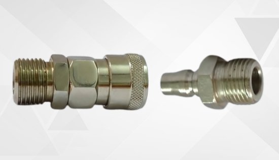
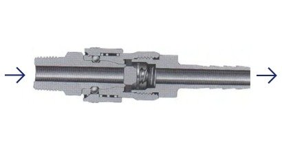
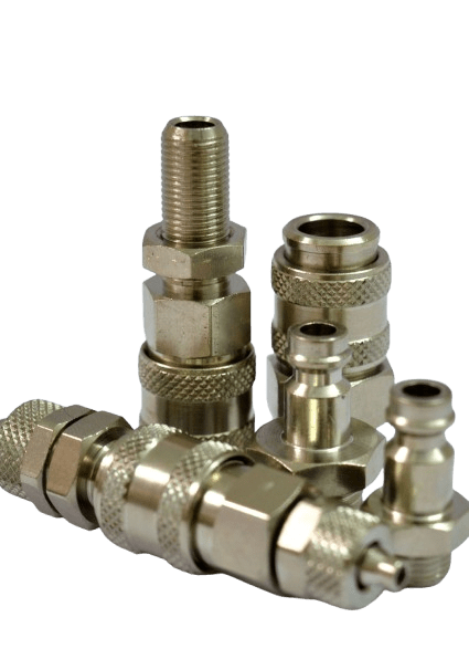
When using quick disconnect couplings, it is crucial to ensure that the media always flows from the coupler to the adapter for optimal performance and safety. Additionally, never attempt to connect or disconnect the coupler while it is under pressure, as this can lead to damage or hazardous fluid leaks. It is also important to avoid applying pulsative pressure to the coupler when it is disconnected, as this can compromise the integrity of the system and potentially cause malfunctions. Following these guidelines ensures safe and efficient operation of the coupling system.
Single Check Valve Coupling- Dimensional Details
Male Coupler (B)
| T | øD | HS | LS |
|---|---|---|---|
| 1/4” | 26.5 | 19.0 | 56.0 |
| 3/8” | 26.5 | 19.0 | 57.0 |
| 1/2” | 26.5 | 22.0 | 59.5 |
Female Coupler (D)
| T | øD | HS | LS |
|---|---|---|---|
| 1/4” | 26.5 | 19.0 | 50.0 |
| 3/8” | 26.5 | 22.0 | 51.0 |
| 1/2” | 26.5 | 27.0 | 52.5 |
Hose Coupler (C)
| SIZE | øD | HS | LS | A | D1 |
|---|---|---|---|---|---|
| 1/4”A | 26.5 | 19.0 | 73.0 | 30.0 | 9.0 |
| 3/8” | 26.5 | 19.0 | 77.0 | 34.0 | 11.3 |
| 1/2” | 26.5 | 19.0 | 81.0 | 38.0 | 15.0 |
Male Adaptor (F)
| T | HP | LP | C |
|---|---|---|---|
| 1/4” | 14.0 | 41.0 | 20.0 |
| 3/8” | 19.0 | 42.0 | 20.0 |
| 1/2” | 22.0 | 45.0 | 20.0 |
Female Adaptor (A)
| T | HP | LP | C |
|---|---|---|---|
| 1/4” | 17.0 | 36.0 | 20.0 |
| 3/8” | 22.0 | 37.0 | 20.0 |
| 1/2” | 27.0 | 38.0 | 20.0 |
Hose Adaptor (E)
| T | HP | LP | C | A | øD |
|---|---|---|---|---|---|
| 1/4”A | 16.0 | 57.0 | 20.0 | 30.0 | 9.0 |
| 3/8” | 16.0 | 61.0 | 20.0 | 34.0 | 11.3 |
| 1/2” | 18.0 | 65.0 | 20.0 | 38.0 | 15.0 |
| Series | SCV 10 | SCV 40 | SC 1 | SS0/SL |
|---|---|---|---|---|
| Size | 1/4”-1” | 1/4”-2” | 1/4”-1” | 1/8”-1” |
| Material | C.S, Brass, SS 304 | C.S, Brass, SS 304 | C.S, Brass, SS 304 | C.S, Brass, SS 304 |
| Seals | Nitrile | Nitrile | Nitrile | Nitrile |
| Locking Mechanism | Ball Lock | Ball Lock | Ball Lock | Ball Lock |
| End Fittings | BSP Female BSP Male Hose Shank | BSP Female BSP Male Hose Shank | BSP Female BSP Male Hose Shank | BSP Female BSP Male Hose Shank |
| Working Pressure | 300PSI | 600PSI | 300PSI | 300PSI |
| T | øD | HS | LS |
|---|---|---|---|
| 1/4” | 26.5 | 19.0 | 56.0 |
| 3/8” | 26.5 | 19.0 | 57.0 |
| 1/2” | 26.5 | 22.0 | 59.5 |

