Double Check Valve Couplings

Double Check Valve Couplings

They are designed for connecting hydraulic lines, hence they are frequently called as Hydraulic couplings. Although it is the main application, they are also used extensively where varieties of other fluids are involved. They are made to withstand pressure up to10,000 psi (700kg/cm2) depending on size & material. They contain valves in both coupler adopter to prevent loss of fluid when disconnected.
It is recommended to use the dust cap & dust plug to prevent contamination of the media when the lines are reconnected and also to increase the life of coupling by preventing damage. Double check valve couplings are available in Brass, Steel, Stainless Steel with a range of body size from 1/4″ to 3”.
Double check valve couplings
Fluids flows in either direction from coupler or adaptor
Features :
Highly air tight.
Built in automatic open & close valve mechanisms.
Different sealing material to suit
Applications:
Agriculture
Plastic Molding
Automobile Industry
Refrigeration
Mobile Hydraulics
Steel Industry
Oil Industry
Test Equipments/Test Beds
High Pressure applications in Hydraulic systems, vacuum, steam, oil, air
For Best Performance:
Use only with recommended media.
Use only with the suggested operating temperature.
Be sure to choose the appropriate type of packing material for your application.
Keep the coupler clean and free of dust.
Use a filter for fluid and air as foreign material may damage the coupler.
Be sure that the thread tape scraps do not enter the line.
Do not over tighten fittings as the threads may be damaged.
Do not hit, bend, or pull. This may cause leakage or damage.
Warning :
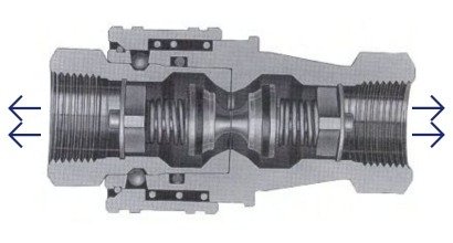
When operating quick disconnect couplings, it is essential to maintain the proper flow direction, ensuring that the media always flows from the coupler to the adapter. To prevent damage or safety risks, never connect or disconnect the coupler while it is pressurized. Additionally, avoid applying pulsative pressure to the coupler when it is disconnected, as this can compromise the system’s integrity and lead to malfunction. Adhering to these precautions helps ensure safe and reliable coupling performance.

Double Check Valve Coupling- Dimensional Details

Untitled design (5)
Coupler (D)
Adaptor
Adaptor (A)
SIZEBøCøDGHAT
1/8”48.822.025.032.814.060.0 
1/4”59.525.529.040.619.074.7 
3/8”65.532.034.045.122.080.4 
1/2”75.038.040.051.527.094.8 
3/4”76.544.045.055.632.098.4B.S.P.
1”85.049.051.063.041.0110.4N.P.T.
1 1/4”99.562.562.572.750.0129.0 
1 1/2”100.6562.562.5102.055.0171.4 
2”99.275.075.0100.070.0163.0 
Coupler
Coupler (D)
Adaptor
Adaptor (A)
SIZE S P øD øD1 L
1/4”A 65.4 64.0 39.6 35.0 105.0
3/8” 65.4 64.0 39.6 35.0 105.0
1/2” 82.4 68.0 39.6 36.0 127.0
3/4” 106.5 100.0 53.8 50.8 168.5
1” 106.5 100.0 53.8 50.8 168.5
Series DCV 10 DCV 100 ISO A/B HIGH PRESSURE DCV 800
Size 1/8”-2” 1/4”-1” 1/4”-2” 3/8”& 1/2” M16, M18 3/8” – 1 1/2”
Material C.S, Brass, SS 304, SS 31 C.S C.S, Brass, SS 304 Hardened Steel,En8 C.S
Seals Nitrile Nitrile Nitrile Nitrile Nitrile
Locking Mechanism Ball Lock Ball Lock Ball Lock Ball Lock Ball Lock
End Fittings BSP Female BSP Male BSP Female BSP Male BSP Female BSP Male BSP Female BSP Male BSP Female BSP Male
Working Pressure 3000PSI 1000PSI 3000PSI 12000PSI 4000 to 9600PSI
1