Straight Thru Couplings

Straight Thru Couplings

They are designed without any valves to provide least resistance to fluid flow. Therefore they require manual shut off valves in both if fluid loss is to be prevented, when the coupling is disconnected.
The wide range of sizes from 1/8″ to 3″ allows the employment in fields ranging from instrumentation to steel mills.
Unrestricted bore of the coupling provides / permits full flow of fluids. These couplings can handle viscous liquids, chemicals.
Series ST-10
Size 1/4” – 3”
Material C.S, Brass, SS 304, SS 316
Seals Nitrile
Locking Mechanism Ball Lock
End Fittings BSP Female Threads, BSP Male Threads, Hose Shank
Straight thru coupling
Fluids flows in either direction from coupler or adaptor
Features :
Suitable for viscous fluids ( such as grease )
Through type coupling ( valveless ) construction greatly reduces pressure loss & enables high flow rates.
Available in various standard body materials, sizes & end fittings, types to cope with a wide variety of applications and conditions.
Applications:
General fluid service
Hydraulic piping
Viscous
Air Compressed air, Gases, fluids, paints, oils, greases, powder, water and slurries.
Operation:
To connect pull back the locking sleeve and push adapter into the coupler.
Release the sleeve and the coupler will lock into the adapter.
To disconnect pull the sleeve back and remove the adapter.
For Best Performance:
Use only with recommended media.
Use only with the suggested operating temperature.
Be sure to choose the appropriate type of packing material for your application.
Keep the coupler clean and free of dust .
Use a filter for fluid and air as foreign material may damage the coupler.
Be sure that the thread tape scraps do not enter the line.
Do not over tighten fittings as the threads may be damaged.
Do not hit, bend, or pull. This may cause leakage or damage.
When using with a vibrating or impact device, install a 30 c.m. length of intermediate hose between the device & the coupler.
Warning :
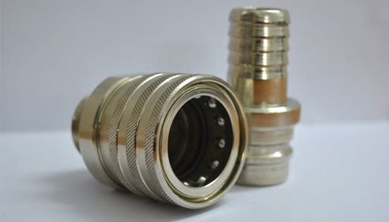
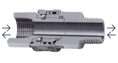
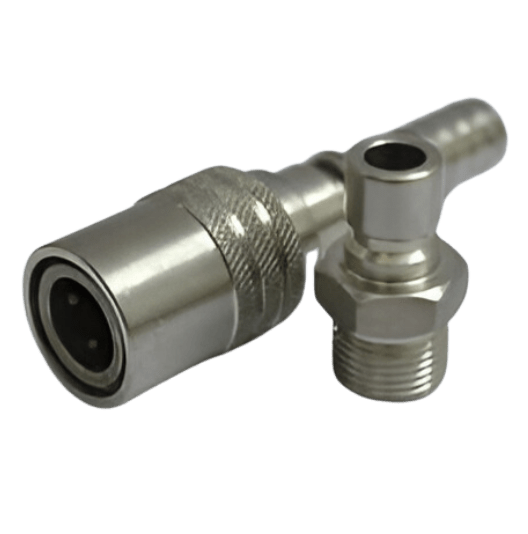
For safe and effective use of quick disconnect couplings, always ensure that media flows from the coupler to the adapter. Never connect or disconnect the coupler while it is pressurized, as doing so can cause leaks or damage to the system. Additionally, avoid applying pulsative pressure to the coupler when it is disconnected, as this may compromise system integrity. Following these precautions ensures reliable operation and prolongs the life of the coupling equipment.

Straight Thru Couplings- Dimensional Details

Male Coupler (B)
Size LS HS A Bsø
1/4” 42 24 6Hex 22 x 24.2 13 7
3/8” 46 28 6Hex 14 x 16.2 13 10
1/2” 52 35 6Hex 22 x 24.2 17 13
3/4” 57 40 6Hex 32 x 34.2 19 18
1-11” 66 54 54øx2Hexx47 22 24
Female Coupler (D)
Size LS HS A
1/4” 32 24 6Hex 22 x 24.2 13
3/8” 35 28 6Hex 14 x 16.2 13
1/2” 45 35 6Hex 22 x 24.2 17
3/4” 45 40 6Hex 32 x 34.2 19
1-11” 49 54 6Hex 36 x 40 22
Hose Coupler (C)
LP Hpø A Bsø
40 17 17 20 6.5 3
59 24 24 30 8 5
64 28 25 34 11 7
75 35 32 39 15 10
86 40 40 48 21 15
Male Adaptor (F)
Size Lp C HP A Bpø
1/4” 38 18 6Hex 14 x 16.2 13 6.5
3/8” 43 21 6Hex 14 x 16.2 13 10
1/2” 49 25 6Hex 22 x 24.2 17 13
3/4” 53 23 6Hex 32 x 37 19 17
1-11” 56 22 6Hex 36 x 40 22 24
Female Adaptor (A)
SizeLpCHPABpø
1/4”34186Hex 17 x 19.6136.5
3/8”38216Hex 21 x 24.21310
1/2”45256Hex 29 x 33.51713
3/4”4423
1-11”472244øx 2Hex 402226
Hose Adaptor (E)
LP C Hpø A Bsø
53 18 14 29 8 5
57 17 18 34 11 7
84 23 23 48 21 15
72 25 22 39 15 10
94 22 42 57 27 19
1